Modern computers are phasing out traditional Parallel Ports, prompting researchers to adopt USB to TTL adapters for precise stimulus triggering in EEG experiments. This study evaluated Cedrus and LabHackers USB to TTL devices across multiple software platforms, showing they provide reliable, sub-millisecond trigger precision comparable to legacy Parallel Ports. Proper configuration and timing validation remain essential to ensure accuracy across hardware and software setups.
OVERVIEW
Modern computers are phasing out analog Parallel Port, which have been widely used for the precise triggering of stimulus onset in research setups. A new serial USB to TTL adapters offer a reliable alternative [1, 2, 3, 4, 5], featuring serial input via a USB port and analog output through a Parallel Port, thus connecting modern an legacy communication protocols. Despite the convenience of this USB to TTL solution, a comparison of time and jitter with the legacy Parallel Port is needed.
EXPERIMENT DESIGN
Cedrus c-Pod and LabHackers’ USB to TTL adapters were tested with different stimulus design software platforms such as E-Prime, PsychoPy, and others [1,2]. The onset time of serial and analog triggers were received by the TTL trigger port of the eego™ amplifier and recorded on eego™ software. The goal was to test these adapters against the conventional Parallel Port. A photodiode was used as the ground truth of stimulation onset, which was needed for Python-based platforms where Parallel Port communication is not currently supported. As a result, this test gives an overview of the time precision of different triggering solutions across different stimulation platforms.
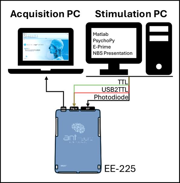
Figure 1: Hardware setup
For each stimulus design software, we used a simple visual experiment in which the screen alternated between black (100 ms) and white (50 ms) images. Triggers were sent prior to the onset of the white screen, with the trigger from USB to TTL adapter occurring first followed by a trigger from the Parallel Port and later with visual stimulation onset.
The results from 1000 trials showed that serial (USB to TTL adapter) and analog (Parallel Port) triggers exhibited sub-millisecond jitter, with serial triggers ranging between 0.15 ms and 0.40 ms (standard deviation) and analog triggers averaging around 0.20 ms. Trigger delays varied across platforms depending on the stimulation platform, hardware specifications of the recording platforms, level of integration that was possible (graphical interface or scripting-based coding of triggers), and finally, dependent on how each experiment design platform handles serial or analog triggers.
These findings confirm that USB-to-TTL adapters are reliable and effective alternatives for visual stimulation on a computer screen (when configured correctly in a PC system setup) to conventional Parallel Ports, offering precise and predictable performance for modern EEG research setups.
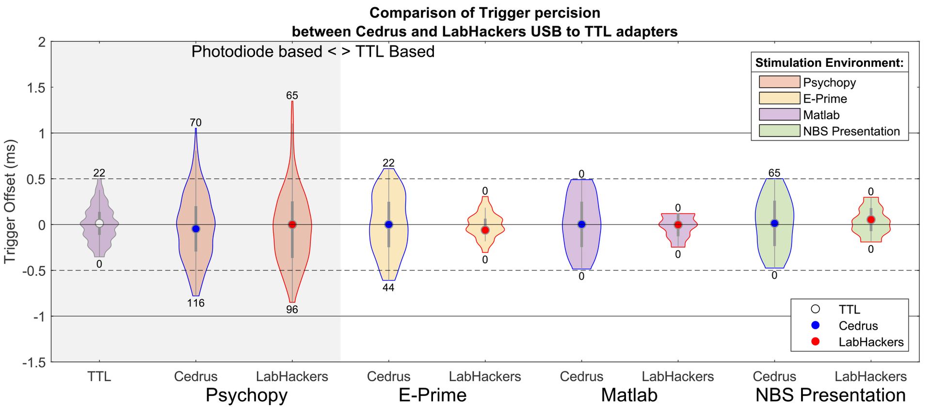 Figure 2: Jitter comparison of serial (USB to TTL adapter) and analog (Parallel Port) triggers. The outer area shows stimulus environment (PsychoPy, E-Prime, etc.), while the inner point shows triggering device (USB to TTL/Parallel port). Each condition contains 1000 trials, where five extreme trials from each side of the distribution are removed. Results for the Python-based platform (leftmost) were calculated by comparing USB to TTL triggers against an onset of visual stimuli reordered with photodiode. All stimulation platforms except PsychoPy showed a sub-millisecond trigger precision.
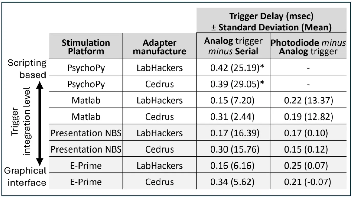
Figure 3: Trigger delay and jitter across USB to TTL solutions. The two rightmost columns show the difference between serial (USB to TTL adapter) and analog (Parallel Port) triggers. The table is sorted by an arbitrary level of integration of analog/serial trigger commands into the stimulation software. Refer to the programming instructions
for examples.
* PsychoPy platform does not support the Parallel Port on Windows 10 and newer machines. Instead, the onset of visual stimuli, recorded with a photodiode, was used.
DISCLIMER: We would like to mention that all the reported latencies across platforms are affected by a variety of factors, such as the hardware specifications of both stimulus and recording PCs and environment-related dependencies based on whether the stimulus software has a stand-alone desktop application or whether it’s Matlab or Python-based. inally, the photodiode-based trigger channel, though reliable, might have a delayed response based on the screen refresh rate as well. We recommend running a timing test to validate trigger consistency for your use case and hardware setup.
GETTING STARTED WITH TRIGGERING
In this section, we provide sample code per platform that users can use to get started with their timing validation and TTL setup. The tips below aim to equip readers with sample code for each stimulation platform; however, in the event of any issues or troubleshooting, each of these platforms provides dedicated support. We would recommend reaching out to them directly for platform-specific questions.
PROGRAMMING INSTRUCTIONS
Cedrus
The C-Pod is a command-based USB to TTL adapter. The full list of commands and examples is available via following links:
- https://cedrus.com/support/xid/matlab.htm
- https://cedrus.com/support/c-pod/tn1717_psychopy.htm
- https://cedrus.com/support/stimtracker/tn1911_eprime.htm
- https://cedrus.com/support/stimtracker/index.htm
Matlab
To initialize the C-Pod:
device = serialport(PortNumber,115200,"Timeout",1);
Here, PortNumber corresponds to the COM port where the C-Pod is connected. Link 1 provides examples of automatic port detection.
To send a trigger:
write(device,sprintf("mh%c%c", TrigCodeBit1_8, TrigCodeBit9_16), "char"); TrigCodeBit1_8 and TrigCodeBit9_16 are two bytes representing a bitmask that sets output lines on the parallel port. These values must range between 1 and 255. The first parameter (TrigCodeBit1_8) controls lines 1–8, and the second (TrigCodeBit9_16) controls lines 9–16. Not all parallel ports support 16 bits/lines of data, but both parameters must be defined every time a trigger is sent.
The “mp” command can be used to set the duration of the signal, followed by a duration in milliseconds encoded as a 4-byte little-endian integer:
write(device, "mp" + four_duration_bytes, "char");
four_duration_bytes has to be a millisecond value in little-endian format. Cedrus provides a helper Matlab function, setPulseDuration, that could be found under Link 1.
Python
Cedrus has developed a dedicated toolbox, pyxid2, for interacting with the C-Pod in Python, simplifying the connection with the C-Pod. This toolbox is integrated into the PsychoPy stimulation platform and can be imported into programming environment using the command “import pyxid2”.
To initialize the C-Pod:
devices = pyxid2.get_xid_devices()
dev = devices[0]
To send a trigger:
dev.activate_line(bitmask=TriggerCode)
Use TriggerCode (1–255) to specify active TTL lines. The dev.activate_line command automatically translates the numeric trigger code into active lines on the parallel port.
The duration of the trigger can be defined using the “dev.set_pulse_duration” function, where the input value is specified in milliseconds.
Presentation NBS
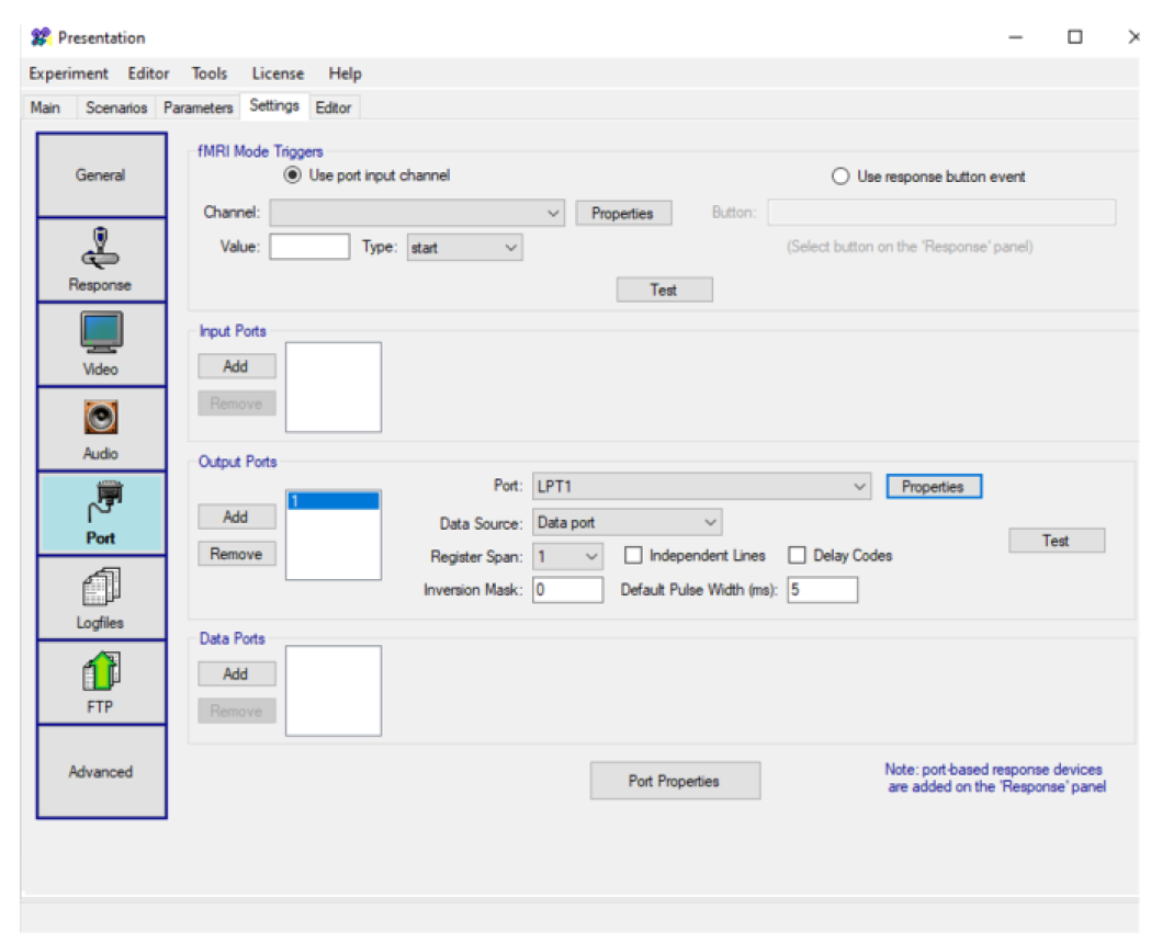
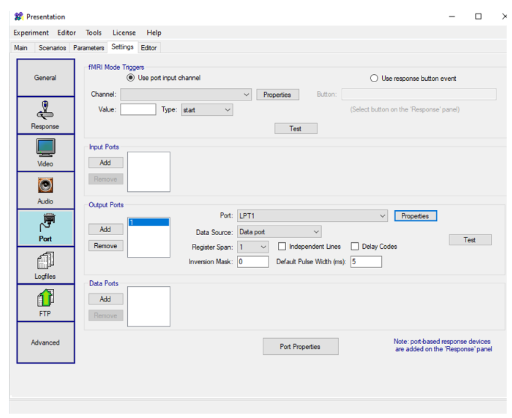
NBS presentation software could send USB to TTL triggers only after the port is defined in GUI.
To initialize the C-Pod:
The port and output ports have to be added and defined as LTP ports. Default settings could be used or adjusted. Port device properties for the USB to TTL interface were set using Rate (155200), Parity (Even) Data bits (8), Stop Bits (1), clear-to-send, data-set-ready out/In set to ON, and data-terminal-ready and request-to-send were set to “enabled”. Also, the “FIFO Interrupt” checkbox was deselected.
Next, it is necessary to open the port in the “begin_pcl” section:
output_port trigUSB = output_port_manager.get_port( 2 );
To send a trigger:
Triggers could be sent in the Task presentation loop by sending sting “mh255” in asci code:
trigUSB.send_code(109); # m in ASCII format
trigUSB.send_code(104); # h in ASCII format
trigUSB.send_code(255); # <- TRIGGER CODE (DECIMAL)
The trigger duration could be set in the “begin_pcl” section by sending the command “mp” + 4 bits of milliseconds in little-endian.
E-Prime
Similarly to Presentation NBS, E-Prime has GUI options to set the ports.
To initialize the C-Pod:
A serial port has to be activated in properties/Devices and set (Image below) to correct COM port (here 4), “115200” Bits Per sec., “8” data bits, Priority as “None”, and Stop bits as “1”.
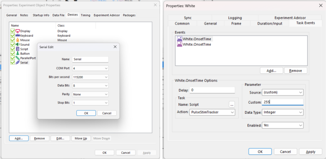
Here an additional function, “PulseStimTracker”, is needed in the “User Script” section. This function will ensure the connection with the adapter and will add an “mh” ASCII letter at the beginning of each trigger. The function is below:
Sub PulseStimTracker (c As Context, lineSettings As Integer)

Dim bytesToRaiseStimTrackerLines(3) As Integer

bytesToRaiseStimTrackerLines(0) = 109 ' ascii m
bytesToRaiseStimTrackerLines(1) = 104 ' ascii h
bytesToRaiseStimTrackerLines(2) = lineSettings # <- Variable TRIGGER CODE (DEC)

Serial.WriteBytes bytesToRaiseStimTrackerLines
End Sub
To send a trigger:
Sending triggers also realized with GUI: in the stimulus properties (e.g., Image presentation) in Tab “Task events” a new action has to be set to a function “PulseStimTracker”. A “Custom” parameter contains a trigger code in decimal format.
The duration of the trigger could also be set in ”User Script” by defining a value with the command “mp” + 4 bits of milliseconds in little-endian.
LABHACKERS
LabHackers USB to TTL adapter is a command-based COM adapter. The complete list of commands and code samples can be found at the following links:
- https://labhackers.com/usb2ttl8.html - Matlab and PsychoPy Examples
- https://osf.io/3kx7g/ - examples for Psychopy, Presentation, Eprime (based on Bridges et al. 2020)
Matlab
Labhackers USB to TTL adapter is recognized as a Serial port.
To initialize the USB2TTL8:
s = serial('COM6','BaudRate', 128000, 'DataBits', 8); %define Serial Port
fopen(s); % Open port for communication
To send a trigger:
To send individual triggers, a string text has to be passed to the Serial port:
fprintf(s, 'WRITE 255 3000\n'); % write to port
The first decimal value after the “WRITE” command defines trigger code that must be in the range between 1 and 255. The second value defines the duration of the trigger in milliseconds.
PsychoPy
To initialize the USB2TTL8:
import serial, time
s = serial.Serial('COM3', baudrate=128000, timeout=0.01)
To send a trigger:
s.write('WRITE 255 3000 0\n') Similarly the first decimal value after the “WRITE” command defines trigger code that must be in the range between 1 and 255. The second value defines the duration of the trigger in milliseconds.
Presentation
NBS presentation software could send USB2TTL triggers only after the port is defined in GUI.
To initialize the USB2TTL8:
The port and output port have to be added and defined as an LTP port. Default settings could be used or adjusted. Port device properties for the USB2TTL8 interface were set using Rate (155200), Parity (Even) Data bits (8), Stop Bits (1), clear-to-send, data-set-ready out/In set to ON, and data-terminal-ready and request-to-send were set to “enabled”. Also, the “FIFO Interrupt” checkbox was deselected.
Next, it is necessary to open the port in the “begin_pcl” section:
output_port trigUSB = output_port_manager.get_port( 2 );
To send a trigger:
trigUSB.send_string("WRITE 255 3000\n"); The two variables represent the trigger code (1-255) and trigger duration (3000 ms)
E-Prime
To initialize the USB2TTL8:
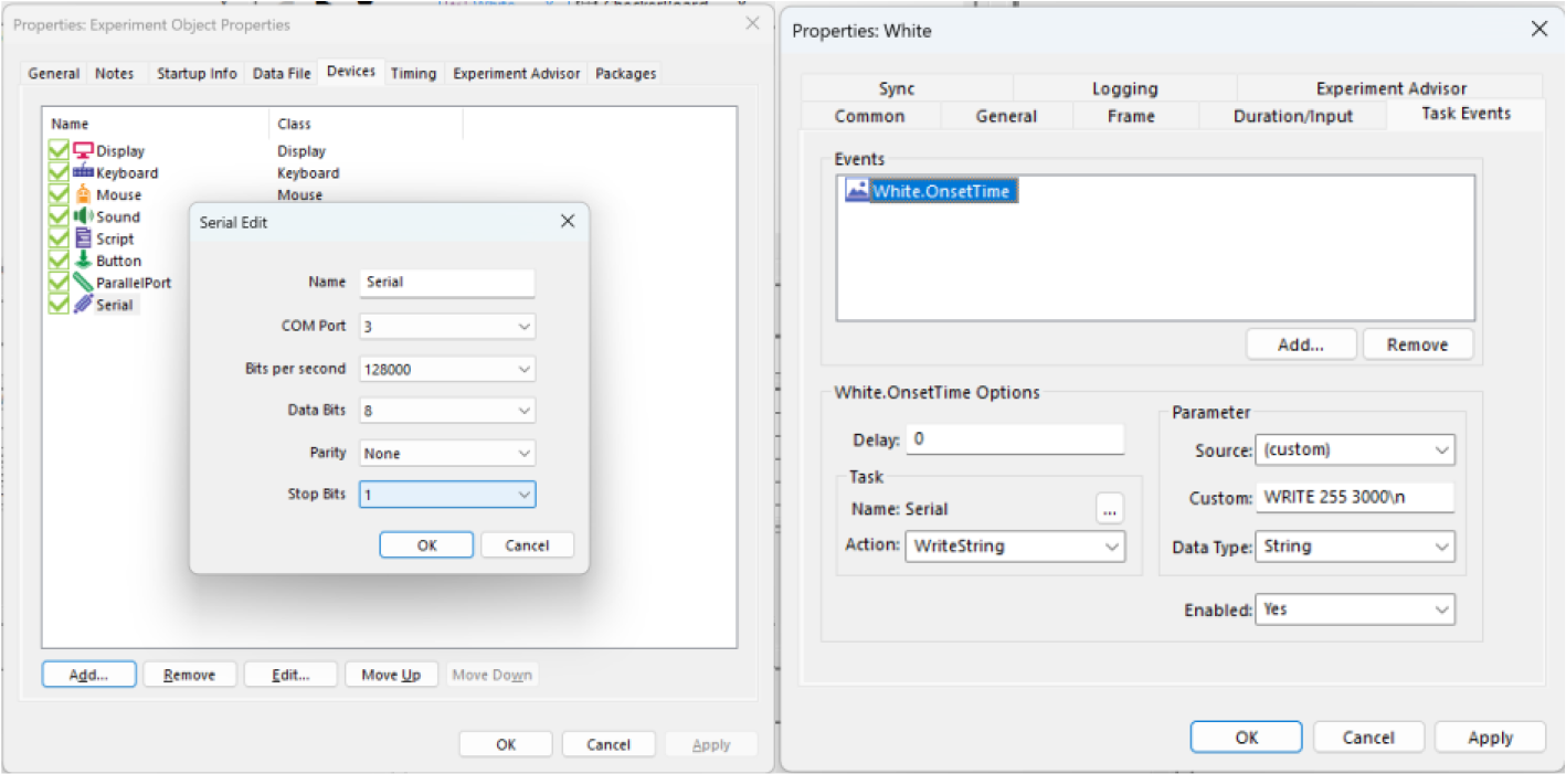
A serial port has to be activated in properties/Devices and set (Image below) to correct COM port (here 3), “128000” Bits Per sec., “8” data bits, Priority as “None”, and Stop bits as “1”.
To send a trigger:
Triggers could be defined in properties of the stimulus (e.g., image) where in Task Events tap a new action could be created (e.g., at the Stimulus OnsetTime) with “WriteString” and a customer message as below:
'WRITE 255 3000 0\n'
The two variables represent the trigger code (1-255) and trigger duration (3000 ms).
REFERENCES
[1] S. Appelhoff and T. Stenner, "In COM we trust: Feasibility of USB-based event marking," Behavior Research Methods , p. 53:2450–2455, 2021.
[2] D. Bridges, A. Pitiot, M. R. MacAskill and J. W. Peirce, "The timing mega-study: comparing a range," PeerJ, p. 27, 2020.
[3] R. Canto, I. Bufalari and A. D’Ausilio, "A convenient and accurate parallel Input/Output USB device," Behav Research, p. 43:292–296, 2011.
[4] R. Gu, "ERP Experimental Design," in EEG Signal processing and feature extraction, Singapore, Springer Nature Singapore Pte Ltd, 2019, pp. 43-70.
[5] N. S. Williams, G. M. McArthur and N. A. Badcock, "It’s all about time: precision and accuracy," PeerJ, p. 15, 2021.
DISCLAIMER
All information provided in this document is intended as a summary only.
For detailed product-related information, please always consult the latest version of the respective product’s user manual. This document is not intended to replace the user documentation. For indications on individual feature certification status (clinical vs. research only) please refer to the user as mentioned earlier documentation.
We have attempted to write this document as accurately as possible. However, mistakes are bound to occur, and we reserve the right to make changes whenever needed or whenever new information becomes available.
All product and brand names in this document are trademarks or registered trademarks of their respective holders.
© Copyright 2023 eemagine Medical Imaging Solutions GmbH.
No part of this document may be photocopied, reproduced, or transmitted in any way without prior written consent from eemagine Medical Imaging Solutions GmbH.