This Application Note provides an overview of how to integrate physiological sensors with ANT Neuro’s eego™ EEG system for multimodal recordings. It explains the differences between bipolar (BIP) and auxiliary (AUX) sensors, their power requirements, and signal types. The document details the hardware integration using the sensebox (XS-271) and bipolar box (XS-270), along with a step-by-step guide for software configuration to ensure accurate data visualization. This setup enables researchers to capture synchronized physiological and EEG data for enhanced analysis in various fields.
OBJECTIVES
This Application Note aims to provide an overview of the different types of physiological sensors that can be integrated with ANT Neuro’s EEG system eego™ for multimodal recordings. This document will include detailed instructions and schematics to guide the user towards a seamless integration of sensors with the EEG system, both at the software and hardware level.
INTRODUCTION: Physiological sensors for multimodal EEG recordings
Physiological sensors, when integrated with EEG systems for multimodal recording, can play a crucial role in enhancing the quality and depth of data collection. By capturing a broader range of physiological signals—such as heart rate, skin conductance, respiration, and muscle activity—these sensors provide complementary information that, when combined and synchronized with EEG data, offers a more comprehensive view of the subject's physiological and neurological states. This multimodal approach is vital in understanding the interplay between brain activity and other bodily functions, facilitating more precise diagnoses, improving real-time monitoring capabilities, and expanding research potential across fields such as neuroscience, psychology, rehabilitation, and human-machine interaction.
BIPOLAR VS. AUXILIARY SENSORS
The two main types of sensors which can be integrated with the eegoTM system are bipolars (BIP) and auxiliary (AUX). The key difference between physiological bipolar sensors, such as ECG, EMG, and EOG, and auxiliary sensors like respiration, GSR, temperature, and accelerometers lies in their power requirements and signal detection methods.
- BIP - Physiological bipolar sensors (ExG) measure the bioelectrical signals generated naturally by the body. These sensors do not require an external power source because they detect the voltage differences between two points on the skin, generated by physiological processes like heartbeats, muscle contractions, or eye movements. Since these signals are inherently present, these sensors operate passively, relying on external amplification (such as that provided by an EEG system) to capture and process the small electrical signals.
- AUX - In contrast, auxiliary sensors (respiration, GSR, temperature, accelerometer) measure non-electrical physiological parameters, such as breathing patterns, skin conductance, body temperature, and motion. These sensors require external power, typically 5V, to function. The power is needed because these sensors often have built-in electronic components—such as amplifiers, transducers, or signal conditioning circuits—that convert the measured physiological parameter into a readable electrical signal. For example, a respiration sensor might use a piezoelectric element to detect changes in chest movement, or an accelerometer may use microelectromechanical systems (MEMS) to detect motion, both requiring a stable power supply for accurate signal generation and transmission.
Thus, bipolar sensors passively capture electrical activity, while auxiliary sensors need external power to actively sense non-electrical physiological signals and convert them into usable data.
HARDWARE INTEGRATION: Sensebox and bipolar box
eego™ mylab and eego™ sports pro amplifiers provide the possibility to access 24 BIP/AUX channel in addition to referential EEG channels. This is achieved by connecting a sensebox (XS-271) or bipolar box (XS-270) to the bipolar port available on the back side of the amplifier.
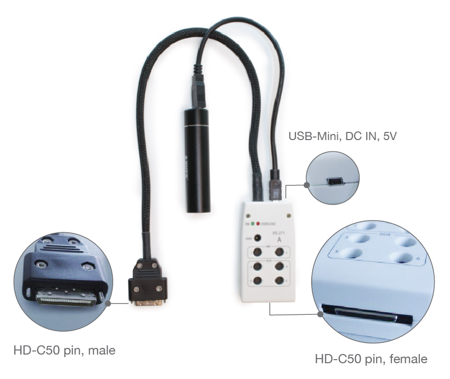
Sensebox
This unit (XS-271) provides access to up to 2 bipolar sensors and 4 auxiliary sensors.
- BIP: channels 1-2 are dedicated to bipolar electrodes. The connector type is a 4-pin binder: positive/negative pins and respective shields.
- AUX: Channels 3-6 are used to connect auxiliary sensors, through a 5-pin binder connector: positive/negative pins, shields and 5V power. This port is compatible with all the XS-35x sensors available in the sensor starter kit.
- DC IN: When AUX channels are being used, sensebox delivers a 5V voltage supply to the sensors through an external power bank which can be connected to the DC IN port via USB-mini.
- GND: A single touch proof connection is available to be used as subject ground if BIP/AUX channels are being recorded independently from EEG data. If EEG is being simultaneously recorded, the patient ground will be automatically drawn from the cap and no additional GND is required.
- Status LEDs: the green “ON” LED will turn on when sensebox is being powered. The red “OVERLOAD” LED is normally off during regular operations. It only turns on as a warning when the total current drawn by the combined AUX sensors in use exceeds the limit of 100mA. In that case, recording should be suspended and some sensors disconnected.
- HD-C50pin male: this connector is used to attach sensebox to the bipolar port on the back of the eegoTM amplifier.
- HD-C50pin female: this port allows for the cascading of multiple sensebox/bipolar boxes, to access more of the total 24 BIP/AUX channels available.
Note: The XS-271 unit comes in 4 variants (A, B, C and D), which can be combined together, as well as with the bipolar box XS-270. The number next to each port indicates the channel number reflected in the software (A: channels 1-6; B: channels 7-12, and so on). Multiple units of the same variant type cannot be cascaded together. For all possible combinations and correct cascading order, please consult the datasheet.
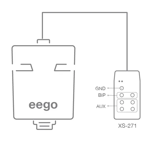
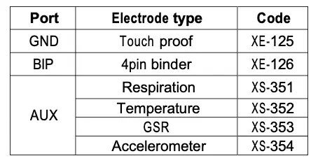
Table 1 – The schematic below shows the product codes and description of the electrodes and sensors which can be connected to
the different ports of sensebox XS-271. The sensors reported in the table are part of the standard sensor started kit, additional individual sensors can be connected to the AUX port of the sensebox. Please consult our technical documentation or contact ANT Neuro’s support team for inquiries regarding additional available sensors.
Bipolar box
The XS-270 unit provides access to up to 6 bipolar channels, through 6 pairs of touch-proof bipolar connectors.
The bipolar box connects to the bipolar port of the amplifier through a HD-C50pin male connector. A female HD-C50pin port is available on the bipolar box for the cascading of multiple units. There are four variants of the bipolar box (A, B, C and D), which can be combined together as well as with the sensebox XS-271. For the correct cascading order please consult the datasheet.
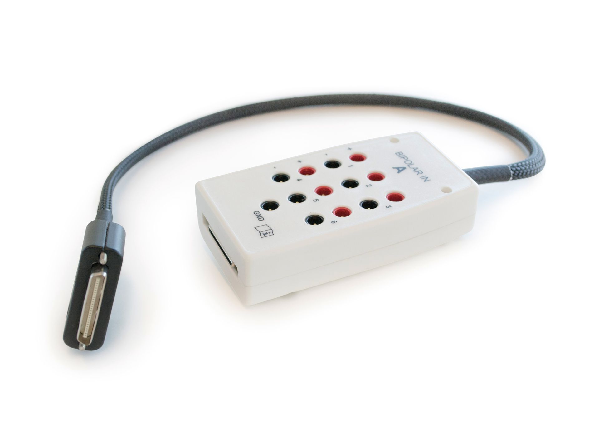
Figure 2: The bipolar box unit XS-270
Note: The XS-270 unit comes in 4 variants (A, B, C and D), which can be combined together, as well as with the sensebox XS-271. The number next to each port indicates the channel number reflected in the software (A: channels 1-6; B: channels 7-12, and so on). Multiple units of the same variant type cannot be cascaded together. For all possible combinations and correct cascading order, please consult the datasheet.

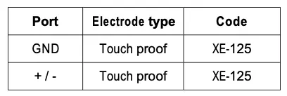
Table 2 – The schematic below shows the electrode type accepted by the bipolar box XS-270
SOFTWARE CONFIGURATION: Amplifier set-up and montage
For a successful multimodal recording, it’s necessary to configure the recording software to match
the desired experimental hardware configuration. This can be done by defining an Amplifier set- up to map the hardware inputs and sensor types which are going to be used. Then, for an optimal online visualization of the data, a dedicated montage should be created to match the defined amplifier set-up. Here visualization parameters like trace colors, scale and filters can be set for each specific peripheral. This section provides a step-by-step guide to do so, for additional information please consult the eego™ extensions user manual.
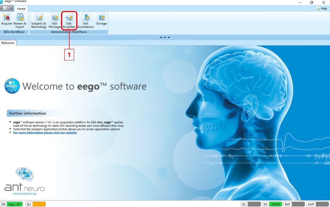
1- From the home page, go to the “Edit Amplifier” page
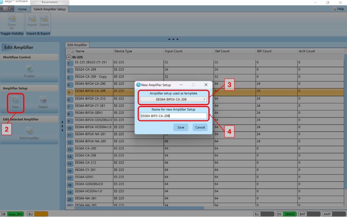
2- Click on “New” to create a new amplifier set-up
3- Select an existing amplifier set-up to use as a template. For example, if you’re using cap CA- 208, select the corresponding EEG64-BIP24-CA-208 set-up, which includes all the EEG channels as well as all the available 24 BIP/AUX channels.
4- Assign a meaningful name to the new set-up, e.g. EEG64-BIP3-CA-208, if you’re going to use only 3 of the available BIP/AUX channels.
5- Scroll through the channel list, you’ll find the BIP/AUX channels listed at the end, after the EEG channels. Select only the channels that are going to be used. In this example: channels 1-3. Change the type field to reflect the type of sensors being used: bipolar or a specific sensor from the drop down menu. You can rename the channel name accordingly, e.g. “ECG” or “EMG”. Note that the order of channels must reflect the hardware unit physically connected, i.e. when a sensebox is connected channels 1-2 are reserved for BIP channels and 3-6 for AUX channels. If a bipolar box is connected channels 1-6 will be all of bipolar type. If multiple cascaded boxes are being used, consult the datasheet to verify the right order of channels. When selecting an AUX sensor, it is possible to define specific calibration points, as well as different signal ranges. Values for each individual sensor are provided in the corresponding section of this document.
6- Save the set-up
7- Finalize the workflow

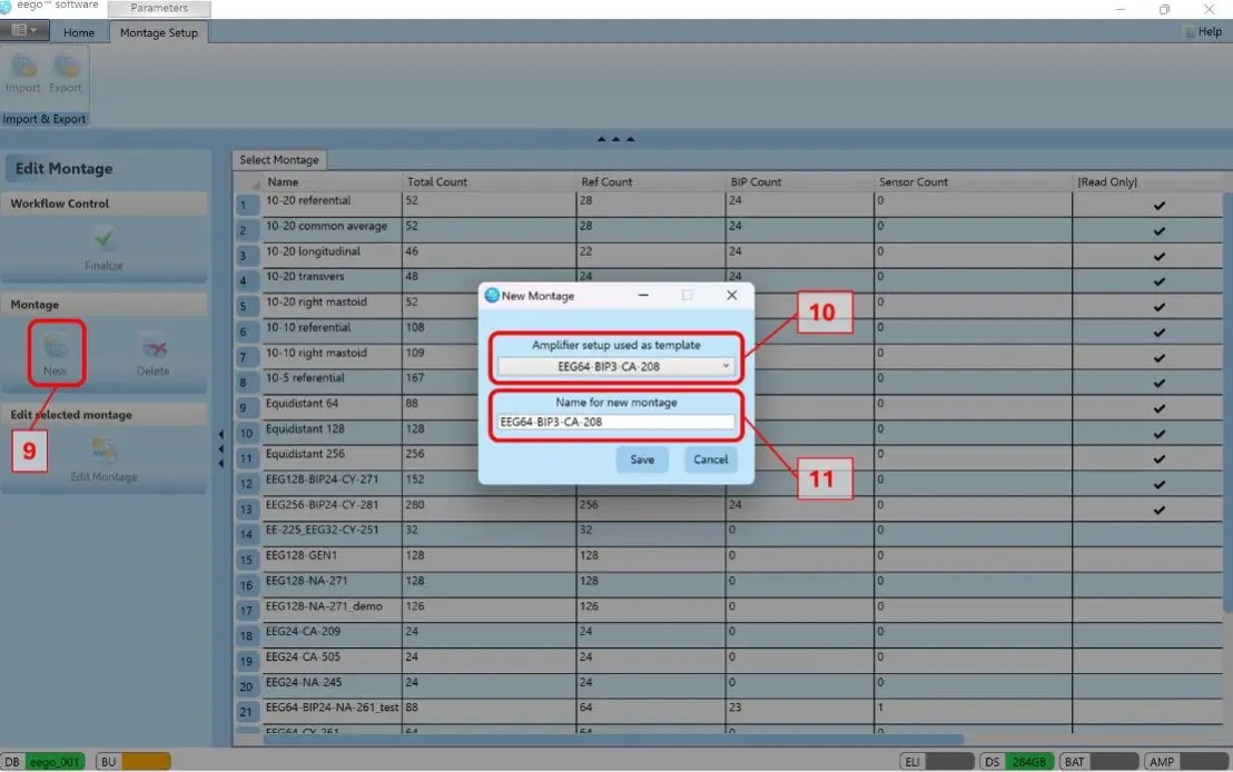
8- From the home page access the “Edit Montage” page

9- Click on “New” to create a new montage
10- Select the amplifier set-up just created
11- Assign the same name to the montage
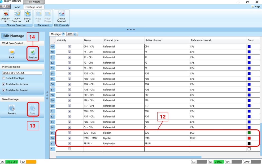
12- The created montage will display the BIP/AUX channels defined in the amplifiers set-up. From
here it is possible to control the appearance of these channels, e.g. trace color, scale, and visualization filters. Recommended values will be provided for individual sensor types in the relative section of this document.
13- Save the montage
14- Finalize the workflow
DISCLAIMER
All information provided in this document is intended as a summary only.
For detailed product related information please always consult the latest version of the respective product’s user manual. This document is not intended to replace the user documentation. For indications on individual feature certification status (clinical vs. research only) please refer to the aforementioned user documentation.
We have attempted to write this document as accurately as possible. However, mistakes are bound to occur, and we reserve the right to make changes whenever needed or whenever new information becomes available.
All product names and brand names in this document are trademarks or registered trademarks of their respective holders.
© Copyright 2025 eemagine Medical Imaging Solutions GmbH.
No part of this document may be photocopied or reproduced or transmitted in any way without prior written consent from eemagine Medical Imaging Solutions GmbH.
Start writing here...